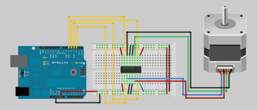
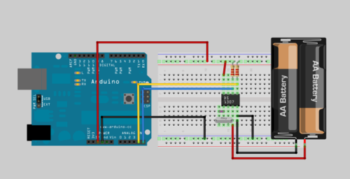
Mostrando entradas con la etiqueta Arduino. Mostrar todas las entradas

30 jun 2015

Sensor de distancia HC-SR04

HC-SR04 es un sensor de distancia por ultrasonidos económico fácil de usar.


Conexionado


El esquema no presenta ninguna dificultad ya que tan solo debemos conectar Vcc a 5v, Gnd a masa y echo y trigger a los pines 7 y ocho respectivamente.


Como funciona


Este sensor funciona igual que la eco localización de un murciélago. Primero emite una serie de sonidos y luego espera a obtener el eco contando el tiempo. Luego conociendo la velocidad del sonido podemos determinar a que distancia esta el objeto. Es lo mismo que nos enseñaron de pequeños con los truenos.


Código arduino


#define echoPin 7 // Echo Pin
#define trigPin 8 // Trigger Pin
#define LEDPin 13 // Onboard LED


int error = 0;
int maximumRange = 200;
int minimumRange = 0;    // Minimum range needed
long duration, distance; // Duration used to calculate distance


void setup() {
pinMode(trigPin, OUTPUT);
pinMode(echoPin, INPUT);
error = 1;
pinMode(LEDPin, OUTPUT); // Use LED indicator (if required)
Serial.begin (9600);
}


void loop() {
/* The following trigPin/echoPin cycle is used to determine the
distance of the nearest object by bouncing soundwaves off of it. */
digitalWrite(trigPin, LOW);
delayMicroseconds(2);

digitalWrite(trigPin, HIGH);
delayMicroseconds(20);

digitalWrite(trigPin, LOW);
duration = pulseIn(echoPin, HIGH);

//Calculate the distance (in cm) based on the speed of sound.
// speedOfSound = 331+0.61*temp; // temp *C
distance = duration/58.2;

if (distance >= maximumRange || distance <= minimumRange){
/* Send a negative number to computer and Turn LED ON
to indicate "out of range" */
if( error ){
Serial.println("Out of Range");
error = 0;
}
digitalWrite(LEDPin, HIGH);
}
else {
error = 1;
/* Send the distance to the computer using Serial protocol, and
turn LED OFF to indicate successful reading. */
Serial.println(distance);
digitalWrite(LEDPin, LOW);
}

//Delay 50ms before next reading.
delay(60);
}

21 feb 2014

El sensor CNY70

Lo cierto es que tras un periodo de inactividad me he vuelto a enganchar otra vez a la electrónica.

En este caso se hará solo una breve entrada sobre el sensor CNY70. No será muy profunda pero eso no implica que con este sensor o equivalentes se pueda llegar mucho más lejos. De hecho podríamos hacer un cuenta vueltas, un medidor de velocidad, podemos guiar un robot sobre una linea negra (o blanca sobre fondo negro), o medir la distancia recorrida por una rueda contando los cambios blanco negro etc.

Con esta pequeña entrada sólo quiero poner una pequeña base para más tarde mezclarlo con un amplificador operacional, un disparador trigger schmitt.

Así que manos, aquí va el esquemático.


Para más información tenemos alternativas a este sensor reflexivo como pueden ser:  QRD1114, QRE1113

10 jul 2012

Comprar electrónica

Como todo en general es normal que al empezar no sepamos encontrar las tiendas que más nos convienen. A modo de ayuda os dejo una tabla donde pongo el precio de los mismos componentes en mismo dia en distintas tiendas. Compara la mediana de todos los productos y hay un total para ver el balance de la tienda.


                    Atmega328  74HC595N  Arduino Uno  LM35     LM358    Total*
rs-online 4,31€ 0,47€ 21,72€2,51€0,28€7,57€
farnell 5,79€ 0,56€ 25,64€1,81€0,23€8,39€
digikey 2,54€ 0,53€ 23,43€1,39€0,40€4,86€
mouser 1,70€ 0,58€ 20,63€ 1,60€0,38€ 4,26€
ondaradio - 0,47€ -1,66€0,62€-
diotronic -0,26€ -0,86€0,12€-
bricogeek 7,00€ 1,60€ 23,48€-- -
futurelect 3,30€ 0,50€ -1,95€0,18€5,93€
sparkfun $5,50 $1,50 $29,95-$0,95-
elactan 6,00€ 0,32€ 21,90€ 2,18€0,41€8.92€
media 3,83€ 0,68€ 22,80€ 1,75€0,32€6,65€


Algunas son muy caras pero tienen piezas que son difíciles o imposibles de encontrar en otras.

La decisión final donde compramos es nuestra (vuestra) pues a veces vale la pena pagar más por la confianza, por atencion o trato al cliente o por tiempo de respuesta.

nota: los precios son orientativos y canvian en el tiempo pero supongo que sirven para hacerse una idea de donde comprar. Además hay que tener en cuenta los portes.

*sin placa arduino

3 jul 2012

Sensor de temperatura MLX90614

Otro sensor de temperatura. Este a diferencia de los demas mide la temperatura por infrarrojos por lo que no necesita contactar con el cuerpo para medir la temperatura. También funciona con el protocolo i2c. Por si se necesitan más detalles aqui va el datasheet del mlx90614

Actualizado:


Y aqui el código .ino para el arduino

#include <Wire.h>
 
void setup(){
Serial.begin(9600);
Serial.println("Setup...");

i2c_init(); //Initialise the i2c bus
PORTC = (1 << PORTC4) | (1 << PORTC5);//enable pullups
}
 
void loop(){
    int dev = 0x5A<<1;
    int data_low = 0;
    int data_high = 0;
    int pec = 0;
 
    i2c_start_wait(dev+I2C_WRITE);
    i2c_write(0x07);
 
    // read
    i2c_rep_start(dev+I2C_READ);
    data_low = i2c_readAck(); //Read 1 byte and then send ack
    data_high = i2c_readAck(); //Read 1 byte and then send ack
    pec = i2c_readNak();
    i2c_stop();
 
    //This converts high and low bytes together and processes temperature, MSB is a error bit and is ignored for temps
    double tempFactor = 0.02; // 0.02 degrees per LSB (measurement resolution of the MLX90614)
    double tempData = 0x0000; // zero out the data
    int frac; // data past the decimal point
 
    // This masks off the error bit of the high byte, then moves it left 8 bits and adds the low byte.
    tempData = (double)(((data_high & 0x007F) << 8) + data_low);
    tempData = (tempData * tempFactor)-0.01;
 
    float celcius = tempData - 273.15;
    float fahrenheit = (celcius*1.8) + 32;
 
    Serial.print("Celcius: ");
    Serial.println(celcius);
 
    Serial.print("Fahrenheit: ");
    Serial.println(fahrenheit);
 
    delay(1000); // wait a second before printing again
}


Os dejo los enlaces para descargar el archivo fritzing y el código fuente

1 jul 2012

Usando LDR

Esta vez usaremos una foto resistencia como excusa para seguir jugando con nuestro arduino. Tanto el montaje como la programación es muy sencillo. Pero antes de nada hay que saber que es una fotoresistencia. Pues no es nada mas que una resistencia que varia su valor en función de la luz que recibe.

Pero que mejor que verlo en este video.


24 jun 2012

Motor paso a paso

En mi caso el motor es un TSY28STH45-0674B

Esquema del montaje: 
 
Y ahora toca el código. Es el mismo que hay en los ejemplos del arduino pero allá va:
 
/* 
 Stepper Motor Control - one revolution
 This program drives a unipolar or bipolar stepper motor. 
 The motor is attached to digital pins 8 - 11 of the Arduino.
 The motor should revolve one revolution in one direction, then
 one revolution in the other direction.  
  
 Created 11 Mar. 2007
 Modified 30 Nov. 2009
 by Tom Igoe
*/

#include 
const int stepsPerRevolution = 200;  // change this to fit the number of steps per revolution
                                     // for your motor
// initialize the stepper library on pins 8 through 11:
Stepper myStepper(stepsPerRevolution, 8,9,10,11);            

void setup() {
   // set the speed at 60 rpm:
   myStepper.setSpeed(60);
   // initialize the serial port:
   Serial.begin(9600);
}

void loop() {
   // step one revolution  in one direction:
   Serial.println("clockwise");
   myStepper.step(stepsPerRevolution);
   delay(500);
  
   // step one revolution in the other direction:
   Serial.println("counterclockwise");
   myStepper.step(-stepsPerRevolution);
   delay(500); 
}

RTC DS1307

Uno de los retos que cruzaran en el camino de cualquier proyecto ensayo  para arduino medianamente serio será guardar la hora. Para ello necesitaremos un RTC podemos usar muchos integrados como pueden ser DS3234,DS1305,DS1307. Las diferencias suelen ser el protocolo de comunicación y/o el tipo de encapsulado. En este caso usaremos el DS1307. Un IC en formato DIP y comunicación i2c o sqw*
Para empezar vamos a montar el tinglado

Y finalmente el código

//
// Maurice Ribble
// 4-17-2008
// http://www.glacialwanderer.com/hobbyrobotics
 
// This code tests the DS1307 Real Time clock on the Arduino board.
// The ds1307 works in binary coded decimal or BCD.  You can look up
// bcd in google if you aren't familior with it.  There can output
// a square wave, but I don't expose that in this code.  See the
// ds1307 for it's full capabilities.
 
#include "Wire.h"
#define DS1307_I2C_ADDRESS 0x68
 
// Convert normal decimal numbers to binary coded decimal
byte decToBcd(byte val)
{
  return ( (val/10*16) + (val%10) );
}
 
// Convert binary coded decimal to normal decimal numbers
byte bcdToDec(byte val)
{
  return ( (val/16*10) + (val%16) );
}
 
// Stops the DS1307, but it has the side effect of setting seconds to 0
// Probably only want to use this for testing
/*void stopDs1307()
{
  Wire.beginTransmission(DS1307_I2C_ADDRESS);
  Wire.send(0);
  Wire.send(0x80);
  Wire.endTransmission();
}*/
 
// 1) Sets the date and time on the ds1307
// 2) Starts the clock
// 3) Sets hour mode to 24 hour clock
// Assumes you're passing in valid numbers
void setDateDs1307(byte second,        // 0-59
                   byte minute,        // 0-59
                   byte hour,          // 1-23
                   byte dayOfWeek,     // 1-7
                   byte dayOfMonth,    // 1-28/29/30/31
                   byte month,         // 1-12
                   byte year)          // 0-99
{
   Wire.beginTransmission(DS1307_I2C_ADDRESS);
   Wire.send(0);
   Wire.send(decToBcd(second));    // 0 to bit 7 starts the clock
   Wire.send(decToBcd(minute));
   Wire.send(decToBcd(hour));      // If you want 12 hour am/pm you need to set
                                   // bit 6 (also need to change readDateDs1307)
   Wire.send(decToBcd(dayOfWeek));
   Wire.send(decToBcd(dayOfMonth));
   Wire.send(decToBcd(month));
   Wire.send(decToBcd(year));
   Wire.endTransmission();
}
 
// Gets the date and time from the ds1307
void getDateDs1307(byte *second,
          byte *minute,
          byte *hour,
          byte *dayOfWeek,
          byte *dayOfMonth,
          byte *month,
          byte *year)
{
  // Reset the register pointer
  Wire.beginTransmission(DS1307_I2C_ADDRESS);
  Wire.send(0);
  Wire.endTransmission();
 
  Wire.requestFrom(DS1307_I2C_ADDRESS, 7);
 
  // A few of these need masks because certain bits are control bits
  *second     = bcdToDec(Wire.receive() & 0x7f);
  *minute     = bcdToDec(Wire.receive());
  *hour       = bcdToDec(Wire.receive() & 0x3f);  // Need to change this if 12 hour am/pm
  *dayOfWeek  = bcdToDec(Wire.receive());
  *dayOfMonth = bcdToDec(Wire.receive());
  *month      = bcdToDec(Wire.receive());
  *year       = bcdToDec(Wire.receive());
}
 
void setup()
{
  byte second, minute, hour, dayOfWeek, dayOfMonth, month, year;
  Wire.begin();
  Serial.begin(9600);
 
/*
  // Change these values to what you want to set your clock to.
  // You probably only want to set your clock once and then remove
  // the setDateDs1307 call.
 
  second = 00;
  minute = 15;
  hour   = 22;
  dayOfWeek  = 5;
  dayOfMonth = 27;
  month      = 11;
  year       = 11;
  setDateDs1307(second, minute, hour, dayOfWeek, dayOfMonth, month, year);
*/
}
 
void loop()
{
  byte second, minute, hour, dayOfWeek, dayOfMonth, month, year;
 
  getDateDs1307(&second, &minute, &hour, &dayOfWeek, &dayOfMonth, &month, &year);
 
  Serial.print(hour, DEC);
  Serial.print(":");
  Serial.print(minute, DEC);
  Serial.print(":");
  Serial.print(second, DEC);
  Serial.print("  ");
  Serial.print(month, DEC);
  Serial.print("/");
  Serial.print(dayOfMonth, DEC);
  Serial.print("/");
  Serial.print(year, DEC);
//  Serial.print("  Day_of_week:");
//  Serial.println(dayOfWeek, DEC);
 
  delay(1000);
}


Hay mucho otro código válido para el DS1307, incluso arduino tiene librerías enteras para él pero este es el que mejor resultado me ha dado.
fuente: en este caso el código lo saqué de el blog de carballada
*no tengo ni idea sobre ello!

Usar tu fuente ATX para alimentar tu arduino

Si eres un tacaño y tienes un PC por allí olvidado y ademas necesitas una fuente de tension para tus proyectos ensayos con arduino siempre puedes usar una fuente ATX de algún PC. Si miramos enn la wikipedia veremos que podemos sacar +12v,+5v,+3,3v,0v,-12v así que seguramente estaremos surtidos en cuanto voltajes. Eso si para poder usar la fuente deberemos puentearla!!
Un detalle importante es que las fuentes suelen tener varios sistemas de protección lo que da un poco de seguridad ya que los amperajes de la misma pueden ser importantes.
Resumen de los pines de la fuente de 24 conectores.

23 jun 2012

Sensor de temperatura TC74V5

Sigo con el tema de los sensores de temperatura. En este caso he optado por el sensor TC74V5. Al ser i2c es de fácil montaje incluso en el primer test lo hice sin resistencia pullup y funcionó todo correcto.
Falta el código para el arduino pues de no ser así quedaria cojo el post.

 
#include "Wire.h"
//wire library
 
#define address 0x4A    // Ojo este numero va segun la version que tengas.

#define delayC 1000
 
void setup()
{
  Wire.begin();
  Serial.begin(9600);
  Serial.println("Init");
}
 
void loop()
{
  Serial.print("temperature in Celsius: ");
 
  float temperature;
 
  Wire.beginTransmission(address);
  Wire.send(0x00);
  Wire.requestFrom(address, 1);
  if (Wire.available()) {
    temperature = Wire.receive();
    Serial.println(temperature);
  } 
  else {
    Serial.println("---");
  }
 
  Wire.endTransmission();
 
  delay(delayC);
}


Sin tener en cuenta si estaba delante de un sensor preciso y sin desviaciones le vi varios defectos para mi proyecto. El primero es que era lento y el segundo tardaba tiempo en recuperarar la temperatura ambiente. Aún así es pronto para hablar mal sobre el pues seguro que tendrá lugar para más de un proyecto.
Y como sigue siendo habitual pongo la fuente dónde creo que saque la información

Moviendo motores DC

Hace tiempo que anduve buscando formas de mover motores de más de 5 voltios con arduino. Una de las primeras que hallé se basaban en transistores en este caso con un transistor tip 120.

sketch arduino tip

Ahora vayamos al código para nuestro arduino:

//////////////////////////////////////////////////////////////////
//©2011 bildr
//Released under the MIT License - Please reuse change and share
//Simple code to output a PWM sine wave signal on pin 9
//////////////////////////////////////////////////////////////////

#define fadePin 9

void setup(){
  pinMode(fadePin, OUTPUT);
}

void loop(){
  for(int i = 0; i<360; i++){
    //convert 0-360 angle to radian (needed for sin function)
    float rad = DEG_TO_RAD * i;

    //calculate sin of angle as number between 0 and 255
    int sinOut = constrain((sin(rad) * 128) + 128, 0, 255); 
    analogWrite(fadePin, sinOut);
    delay(15);
  }
}

Fuente de la información bildr.com